GridHub V1.0 Installation Guide
Intended Use
This device is intended for use in electrical systems to record and transmit electrical consumption data . It should not be used for any other purpose other than that specified by the manufacturer.
In the Box
The standard components included to establish a BC Capacity Monitoring Service for a single installation are:
IMPORTANT: Confirm all parts are present before starting installation. The number of CT Clamps included will be as requested in the purchase order. One for single phase monitoring in smaller locations, or three for three-phase monitoring in larger locations.
- 1 x Blackcurrent GridHub Monitor
- 1 x C5 clover leaf cable (for single phase voltage collection) OR
- 1 x Molex 6-pin wiring hardness
- 3 x CT Clamps
| GridHub Monitor | Power Cable | CT Clamp |
|---|---|---|
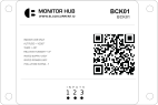 |  |  |
IMPORTANT: Confirm all items have been supplied. Ensure that you have the correct CT clamps supplied as per the BoM supplied with the Work Order.
Installation
Installation of the Blackcurrent GridHub energy should be performed by an approved installer or a registered electrician. The installation process is as follows:
-
On site, confirm there is sufficient space in the meter enclosure/switchboard for the monitor and CT Clamps.
-
Connect each of the CT clamps to the power supply as close to the Retailer's meter as possible. CT Clamps need to be fitted before any sub-feeds branch off.
Single Phase
The monitor requires a 230BV main power supply via the supplied C5 cable. Locate or install a power point as close as possible to the monitoring location. Inside the enclosure is ideal if possible.
Fit the supplied split-core CT clamps around the live cable and fitting the 2-pin molex connector to the corresponding port.
We recommened locating CT clamps according to the following designations:
| Channel | Designation |
|---|---|
| 1 | Import |
| 2 | Export |
| 3 | Generation |
Three Phase
For 3-phase configuration, power is provided via a 6-pin molex wiring harness. This will enable voltage data for each phase to be collected.
Wire according to the following:
| Pin | Phase |
|---|---|
| Pin 1 | No function |
| Pin 2 | No function |
| Pin 3 | Phase 1 |
| Pin 4 | Neutral |
| Pin 5 | Phase 2 |
| Pin 6 | Phase 3 |
| Molex Wiring Diagram |
|---|
 |
CT Clamps
Fit the supplied split-core CT clamps around the cable(s) then insert the 2-pin molex connector to the corresponding ports as per the allocation below:
| Channel | Designation |
|---|---|
| 1 | Phase 1 |
| 2 | Phase 2 |
| 3 | Phase 3 |
NOTE: The clamps are directional so make sure they are fitted correctly. There is an arrow in the side of the clamp with shows the way the electricity should be flowing through the clamp P1 = the side facing the retailer meter
Device Connectivity
The LED located on the bottom left of the front face indicates the following states:
| LED State | Meaning |
|---|---|
| RED (flashing) | Device is attempting connection to the cellular network |
| YELLOW (flashing) | Device is connected to the cellular network and attempting to connect to the cloud |
| GREEN (solid) | Device is connected to both the cellular network and the cloud |
Technical Specifications
| ACCEPTABLE USAGE | INDOOR USE ONLY |
| ALTITUDE | < 2000 FT |
| OPERATING TEMPERATURE | 10oC - 50oC |
| RELATIVE HUMIDITY | 80% |
| POWER SUPPLY | 230VAC |
| INGRESS PROTECTION | IP2X |